


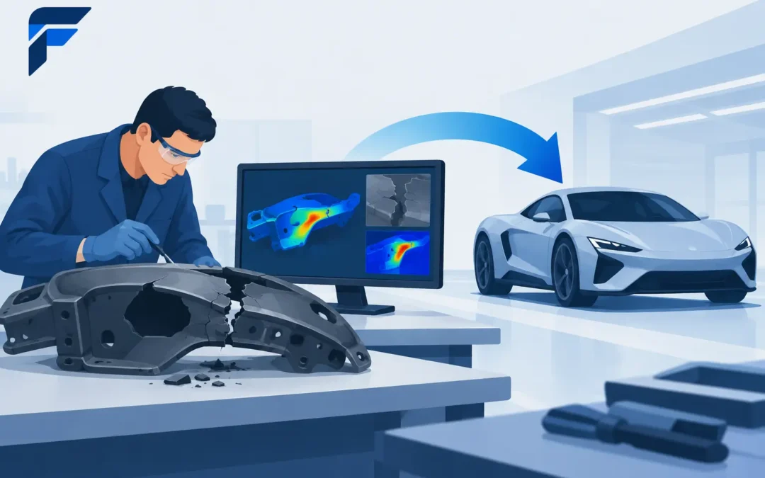
A broken upright after a curb strike, an inverter that derates halfway through endurance, or a car that misses its acceleration target is not just a setback. It is evidence. Prototype failure analysis gives Formula Student teams a disciplined way to turn that evidence into the next design decision, rather than another late-night replacement part.
The strongest teams do not treat failure as something to hide before competition. They make it visible, measurable, and useful. That approach protects limited budgets, builds trust between subteams, and creates a car that has been validated rather than simply assembled.
What Prototype Failure Analysis Actually Means
Prototype failure analysis is the structured process of determining what failed, how it failed, why it failed, and what must change to prevent a repeat. The distinction matters. Replacing a failed component restores the car. Understanding the failure improves the program.
For a student team, the process usually sits at the intersection of mechanical design, electronics, controls, manufacturing, and operations. A cracked suspension bracket may involve a load assumption, a weld sequence, material selection, driver behavior, tire setup, or a sensor that failed to reveal the loading event. Looking only at the broken bracket can produce a fix that fails again for a different reason.
A useful investigation separates three layers. The failure mode is what happened, such as a bolt loosening or a cell exceeding temperature limits. The mechanism is the physical or logical process that led to it, such as vibration-induced loss of preload or insufficient cooling flow. The root cause is the underlying condition that allowed it, such as an incorrect torque procedure, an unvalidated clamp design, or a requirement that never accounted for a realistic duty cycle.
This is not about finding someone to blame. It is about finding the first correct decision that would have stopped the failure chain.
Start Before the Prototype Breaks
Failure analysis is far more effective when the team prepares for it during design and testing. If a component fails with no load data, no build record, and no clear revision history, the investigation becomes speculation.
Every critical system should have a simple validation plan before the car reaches the test track. Define what success looks like, which conditions will be tested, what data will be recorded, and who has authority to stop the test. For high-risk items, agree on the expected failure boundary as well. A suspension pushrod test, for example, should not only confirm that it survives a target load. It should reveal its margin, its likely deformation pattern, and whether the fixture represents real mounting conditions.
Configuration control is equally valuable. Record the CAD revision, material batch where relevant, manufacturing process, software version, torque values, alignment settings, tire pressures, and any trackside changes. This may sound administrative, but it prevents one of the most common Formula Student problems: analyzing a failure on a car that is no longer configured as it was when the failure occurred.
At FS Alpe Adria, a technically convincing car is not only one with clever engineering. It is a car whose team can explain its decisions, validation, risks, and learning with confidence.
The First Hour After a Failure
The urge to repair immediately is understandable, especially when test time is short. Resist it long enough to preserve the facts. The first hour often determines whether the team learns something lasting or only gets back on track temporarily.
Begin by making the situation safe. Isolate high voltage, secure the vehicle, control fluids, and make sure no one continues testing around a potentially unsafe condition. Then document the evidence before parts are removed or cleaned. Take wide photos to show the system context and close photos of damage, fasteners, wiring, surfaces, and witness marks. Capture the vehicle state, weather, track condition, driver feedback, dashboard warnings, and available logs.
A short factual timeline is powerful. Record when the test began, when the first symptom appeared, what changed immediately beforehand, and when the failure became clear. Keep observations separate from theories. “Left rear damper oil visible after lap six” is an observation. “Damper overheated because the setup was too stiff” is a hypothesis that still needs proof.
If the failure is intermittent, do not dismiss it because the car works again after a reset. Intermittent electrical faults, thermal limits, and software timing issues often become more expensive when they are treated as one-off events.
A Practical Prototype Failure Analysis Workflow
A repeatable workflow helps teams investigate under pressure without skipping the basics. The exact tools can vary, but the sequence should remain consistent.
- Contain the failure. Stop use of affected systems, inspect for related damage, and decide whether a temporary repair is safe enough for controlled testing.
- Preserve evidence. Save logs, quarantine failed parts, label their installed position, and photograph the condition before disassembly.
- Define the failure clearly. State the expected function, the actual outcome, and the operating conditions. Avoid vague labels such as “electronics issue.”
- Test competing causes. Use inspection, measurement, simulation, bench testing, and controlled vehicle tests to eliminate explanations rather than selecting the most familiar one.
- Implement and verify corrective action. Confirm the change fixes the cause, does not introduce a new weakness, and works under representative conditions.
The fifth step is where many teams stop too early. A revised mount that survives a static shop test is not automatically ready for endurance conditions. Verification should match the original failure environment as closely as possible. That may mean vibration, heat cycling, repeated load cases, wet conditions, or full-duty software operation.
Tools That Make the Investigation Stronger
You do not need a laboratory full of expensive equipment to run a credible analysis. You need the right level of evidence for the decision at hand.
For mechanical failures, start with visual inspection, dimensional checks, torque verification, and a review of load paths. Fracture surfaces can reveal useful clues: a smooth region may indicate progressive fatigue, while a rough, granular surface can point toward sudden overload. Be careful with interpretation, though. A part can fail in overload after being weakened by fatigue, corrosion, poor surface finish, or an unintended stress concentration.
For electrical and high-voltage systems, combine fault logs with measured voltage, current, temperature, insulation status, and connector condition. Heat discoloration, loose crimps, and pin damage are evidence, but so are missing logs and inconsistent timestamps. A fault code is a starting point, not a verdict.
For software and controls, reproduce the problem with a known vehicle configuration and saved inputs whenever possible. Review state transitions, sensor plausibility checks, timing, calibration limits, and error handling. A control issue may originate in hardware noise, a mechanical vibration source, or a calibration assumption, so cross-subteam reviews matter.
Simple methods such as the 5 Whys, fault tree analysis, and fishbone diagrams can help structure discussion. They are useful only when backed by evidence. Asking “why” five times does not guarantee a root cause if every answer is an untested assumption.
Avoid the Most Expensive Team Habits
The biggest analysis mistakes are rarely technical. They are process mistakes made by capable people under time pressure.
The first is replacing parts without recording the original condition. The second is changing several variables at once, then being unable to tell which change worked. The third is allowing subteams to investigate in isolation when interfaces are involved. A cooling problem can become a battery problem, a mechanical packaging problem, and a controls problem at the same time.
Another costly habit is treating every failure as a component issue. Sometimes the component is fine and the requirement was wrong. A part designed for one peak load may fail because the real duty cycle contains thousands of smaller cycles. A battery enclosure may pass a static check but create serviceability delays that pressure the team into unsafe rushed work. Good failure analysis challenges the original assumptions, not just the final hardware.
Finally, distinguish between a temporary containment action and a permanent corrective action. Safety wire, an added brace, or a conservative software limit may be the right choice for finishing a test day. It is not necessarily the final design solution. Label it honestly in the log and create an owner and deadline for the permanent fix.
Turn Findings Into Team Knowledge
A failure report should be short enough that people will read it and precise enough that next year’s team can use it. Include the failure statement, impact, evidence, root cause, contributing factors, immediate containment, corrective action, verification plan, and any rule or safety implications. Add photos, data excerpts, and part revisions where they clarify the story.
Discuss major failures in a cross-functional review. The goal is not a long meeting. It is alignment: everyone should understand what changed, what remains uncertain, and whether the risk is acceptable for the next test. This is where a team’s network becomes as valuable as its individual knowledge. A manufacturing lead may notice a process variation that the designer cannot see. A driver may describe a vehicle behavior that explains a load spike. A scrutineer or mentor may recognize a safety concern early.
The best outcome is not a prototype that never fails. It is a team that fails safely, learns quickly, documents honestly, and returns to the track with a better question than it had before.